Gears
Gears, like sprockets and pulleys, are used in power transmission for three common applications: changing the direction of power, changing the amount of torque, and changing RPM. Gears are a less common transmission option than chain, but are still very viable for most use cases. Gears are equally as reliable as chain, but can’t be used for transferring power over long distances. Many teams dislike gears when using kit-based channels because the hole pattern limits which combinations of gears can be used. Consequently, it may be difficult to achieve a desired specific gear ratio. However, with extrusion systems, it’s very easy to use different ratios, since the gears can be moved around in extrusion.
Term
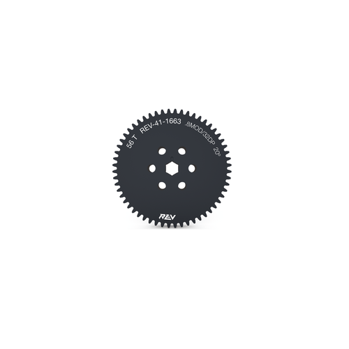
Gears are made in different materials, with the most common being 7075 aluminum. Never mesh plastic and metal gears together. It is acceptable to mesh different types of metal gears together, as long as they have the same diametral pitch. It is advised to stay away from TETRIX aluminum gears as they wear down very easily. Some REV gears are made out of Delrin, a self-lubricating plastic. It is a durable material, but keep in mind that it is very possible to strip the bore using a plastic gear. Thus, we advise using the REV Hex Hub Strengthener to avoid stripping the bore on Delrin gears.
Bevel gears are a special type of gear that allows power transmission in two different planes. It is especially useful in tight spaces where a regular motor mounting position would not work.
Pitch Diameter Calculation
Pitch circle refers to an imaginary circle that contacts the pitch circle of any other gear with which it is in mesh. Basically, each gear has a pitch circle. When gear 1 is meshed with gear 2, the pitch circles of both gears should touch exactly in the middle of where the teeth interlock with each other.
Meshing Gears
Term
- Mesh
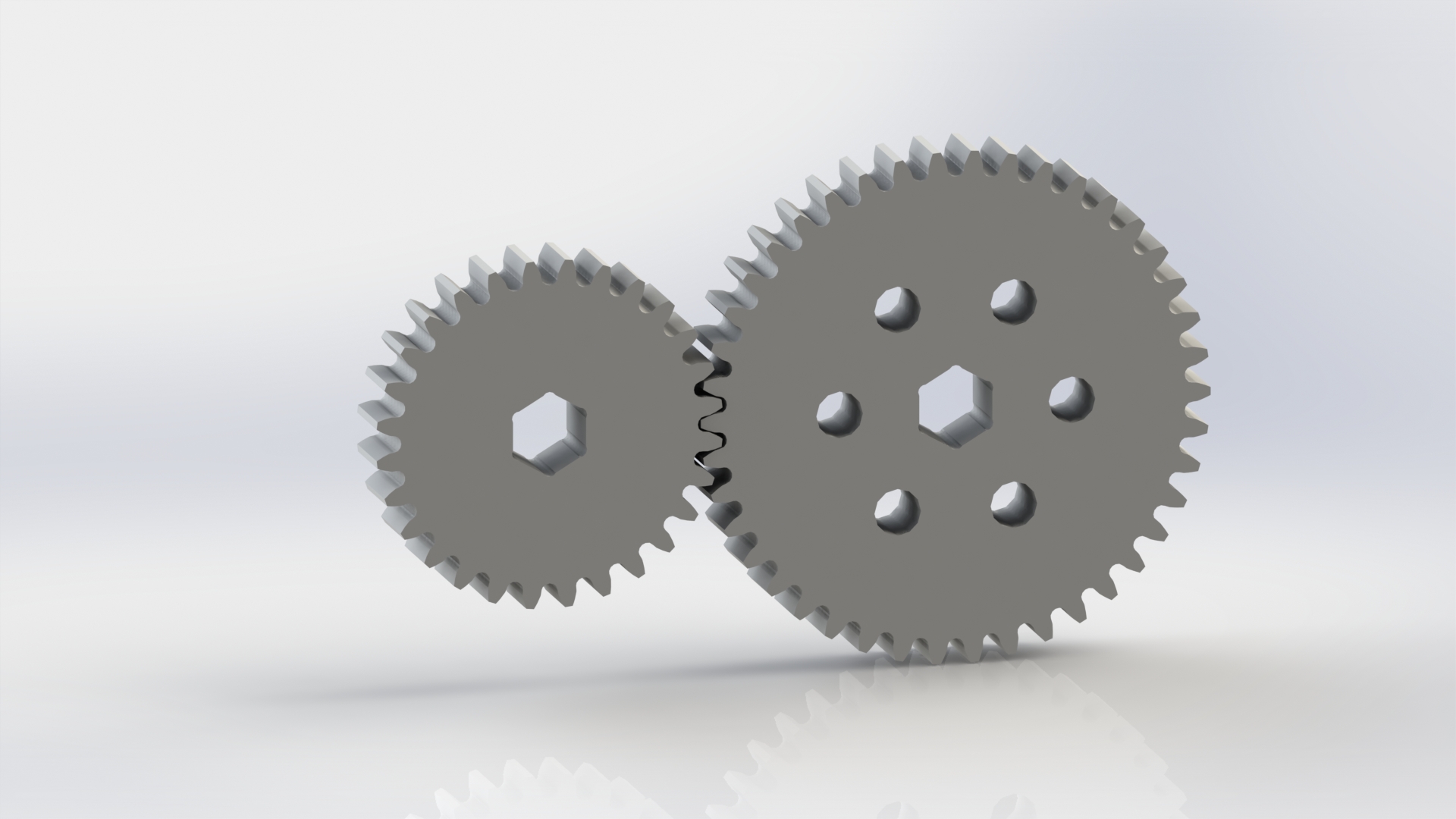
Meshing refers to the overlapping contact between a gear tooth and another gear tooth, chain and sprocket, or belt and pulley.
A proper mesh is essential to ensure maximum torque transmission. Too little mesh can result in no power transfer, derailment or gears grinding/wearing down faster. Too much mesh can produce unwanted friction and introduce inefficiencies within the drive system.
When meshing gears, it is important that the gears are not too loose nor too tight. If the gears are too loose, the teeth will easily wear out, decreasing its longevity. If the gears are too tight, however, they will have too much friction and possibly grind or bind up. The ideal way to mesh gears are to make sure the teeth interlock and just touch the base of the gear.
Attention
If possible, it’s best to avoid meshing gears with a clamping motor mount – due to the sensitivity of the mesh, even the slightest movement of the motor inside the clamping mount can cause the gears to slip or damage each other.
Calculating center-to-center distances using gears is quite simple. In order to calculate the desired center distance between two given gears, you must know the number of teeth for each gear and the diametral pitch of your gears (the number of teeth per inch of the gear’s diameter). With these two pieces of information, you can use the equation \(D=\frac{T_{1}+T_{2}}{P}\). In this equation, \(D\) is the distance between the center of both gears, \(T_1\) and \(T_2\) are the number of teeth of each gear in question, and \(P\) is the diametral pitch of the gears.
The module (abbreviated MOD) of a gear is used similarly to diametral pitch. It is the number of millimeters of the gear’s diameter per tooth of the gear. The equation to find center distance \(D\) is \(D = \frac{(T_{1} + T_{2}) * M}{2}\), where \(T_{1}\) and \(T_2\) are the number of teeth of each gear in question, and \(M\) is the module of the gear.
Note
Be sure to never mesh gears that are not of the same diametral pitch. (A notable exception is 32 diametral pitch and 0.8 MOD gears. These are close enough to be perfectly fine.)
Additionally, it is possible to average the pitch diameters of the two gears to find the correct center-to-center distance.
Correct gear mesh
As with sprockets, it is important to line up the gears so that they do not accidentally slip. Especially when using extrusion, it is possible that the gear may not be parallel to the extrusion, as the two supporting ends may not be perfectly in line with one another. It is imperative that the gear be lined up as straight as possible to prevent damage or gear binding.
It is highly recommended to use white lithium grease or a similar lubricant between the gears to reduce friction and possible binding.
Advantages
Gears are a solid and proven power transmission method. Early examples of gears date back to the 4th century BC, so you’re using technology with millennia of development behind it. When it comes to gears, there’s not much that we haven’t figured out.
Gears are simple to use with both channel and extrusion. On channel, your gears are already spaced correctly - you just need to choose the right pair of gears. Extrusion gives you even more flexibility - just slide your gears into mesh, and you can have whatever ratio you want.
Gears can give you big reductions in small areas. Depending on the gear combination, one can achieve big ratios in reduction in very small spaces (for example, a 10 tooth gear and a 100 tooth gear will take much less space than a 10 tooth sprocket and a 100 tooth sprocket).
Gears require no tensioning: once the spacing is correct, the gears will operate quickly. Unlike chain or belt, there is nothing further transferring the power, which cuts out the need to properly tension chain or belt. This of course has the drawback of not being able to transfer power far distances.
Disadvantages
Sometimes, the ratio you want might not be easy to build. Channel spacing limits gear ratios, but this can be circumvented with compound ratios and a bit of creativity.
Long distance power transfer is impractical with gears. If you need to transfer power long distances, gear combinations can become complicated very quickly, so belt/chain is preferable.
Meshing gears can be tricky. It’s only made worse by the sensitivity of a gear mesh. However, channels do solve this problem, providing pre-spaced holes to easily mesh your gears. Do keep in mind that gear mesh may not be perfect, even with channel.
Gears usually wear faster than sprockets if there is too much friction between the gears. Teams can use white lithium grease or similar lubricant to help remedy this problem.
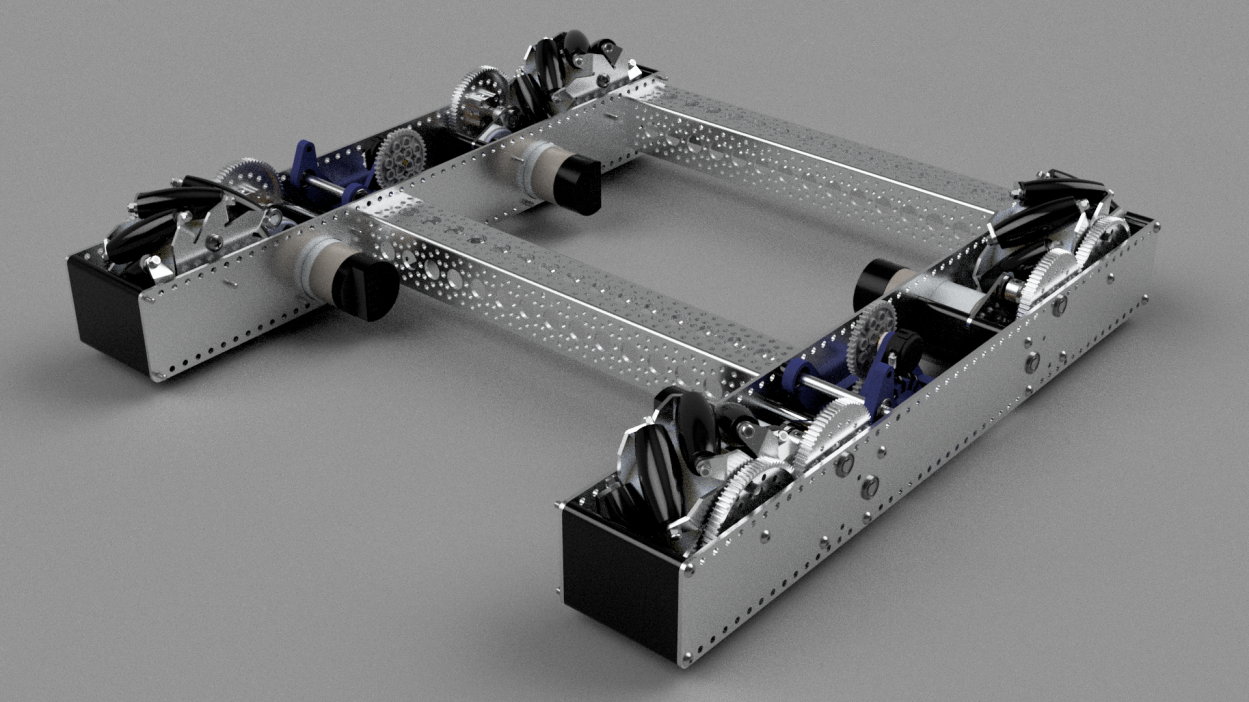
11115 Gluten Free gear-based drivetrain
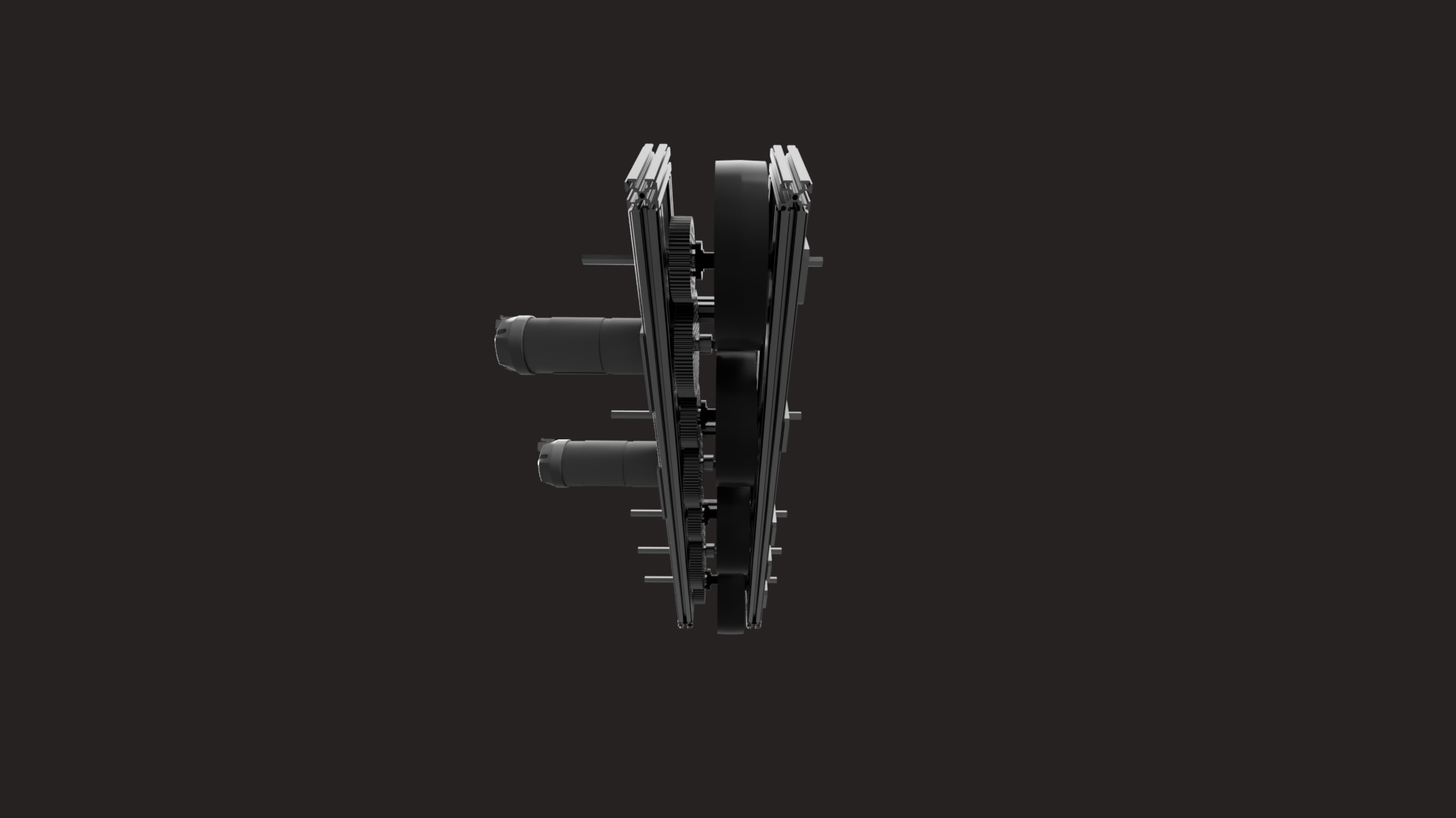
13075 Coram Deo Robotics, Rover Ruckus gear-based drivetrain